|
MQ devices match XF power supply and I/O specs |
Below you will find the minimum and maximum admissible values of digital inputs and outputs as well as analog voltage and current inputs, and also cLAN consumption and power supply.
cLAN-1520-XF / cLAN-3524-XF
Parameter |
Condition |
Minimum |
Maximum |
Units |
Input voltage |
|
10 |
30 |
Vdc |
Average consumption |
@ 24 Vdc @ 12 Vdc |
|
100 190 |
mA |
cLAN-1205-XF / cLAN-2205-XF
Parameter |
Condition |
Minimum |
Maximum |
Units |
Input voltage |
|
10 |
30 |
Vdc |
Average consumption |
@ 24 Vdc @ 12 Vdc |
|
50 80 |
mA |
cLAN-3404-XF
Parameter |
Condition |
Minimum |
Maximum |
Units |
Input voltage |
|
10 |
30 |
Vdc |
Average consumption |
@ 24 Vdc @ 12 Vdc |
|
90 170 |
mA |
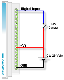
To activate the digital inputs a continuous voltage must be applied externally. This source of power has to share the GND terminal with the power supply of the equipment. If necessary the same power supply that feeds the cLAN can be used. The input is of a Sinking type. It accepts sensor or PNP Sourcing type devices.
| cLAN-3524-XF (A, B and C versions) | cLAN-3524-XF (D version) | ||||||||||||||||||||||||||||||||
|
|
cLAN-2205-XF
Parameter |
Minimum |
Maximum |
Units |
Activated input |
7 |
50 |
Vdc |
Input impedance |
280 |
|
KΩ |
Count frequency |
|
45 |
Hz |
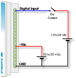
We now show two examples of how to connect an input, directly from the same source feeding the equipment and from an external source where we can clearly see that they must share the common Terminal.
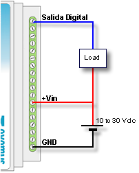
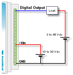
Digital outputs are of the open collector type. The load to be connected must be fed with an external power supply and they have to share the GND Terminal with the equipment power supply. If necessary, the same power supply used to feed the equipment can be used.
The output type is NPN Sourcing type (Open collector).
| cLAN-3524-XF (A, B and C versions) | cLAN-3524-XF (D version) | ||||||||||||||||||
|
|
cLAN-2205-XF
Parameter |
Maximum |
Units |
Withstand voltage |
50 |
Vdc |
Current |
200 |
mA |
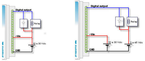
When the digital output is used to actuate a relay coil a protection diode must be added to the connection to avoid damage to the output of the equipment. This must be connected in reverse, that is the anode to the output terminal of the equipment and the cathode to the positive terminal feeding the relay. The relay must be fed using an external power supply, sharing the GND terminal with the power supply of the equipment, or if necessary the same power supply feeding the cLAN can be used.
The following graph shows how to connect a relay to a digital output of the equipment.
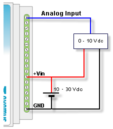
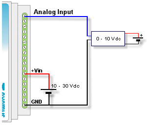
cLAN-3424 Analog inputs refer to the GND Terminal of the equipment, consequently, the power supply used to feed the sensor must share the GND terminal with the equipment.
Parameter |
Value |
Units |
Full scale |
10 / 1 |
Vdc |
Resolution |
1 / 0.1 |
mV |
Input impedance |
11.4 |
KΩ |
The following two examples show how to connect and analog voltage input for a single power supply or for independent power supplies.
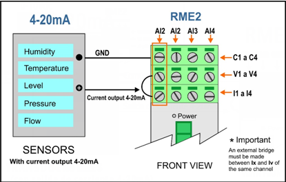
cLAN-3524-XF - Current inputs (4-20mA)
Parameter |
Value |
Units |
Full scale |
20 |
mA |
Resolution |
10 / 1 |
uA |
Shunt resistance |
100 |
Ω |
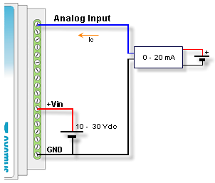
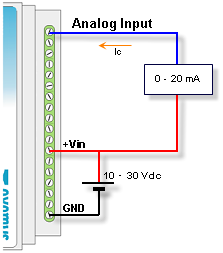
The following two examples show the connection of a 4 – 20 mA sensor sharing the power supply with the equipment for passive sensors or for active sensors with independent power supply.
cLAN-3404-XF - Voltage inputs (0-10V / 0-1V)
Parameter
Value
Units
Full scale
10 / 1
Vdc
Resolution
1 / 0.1
mV
Input impedance
>600
KΩ
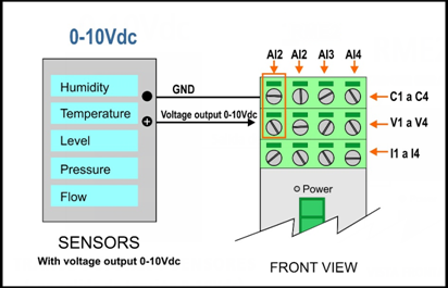
Analog inputs are diferential (two terminals per input)
Sensors with voltage output (0-10V) can be connected to the device as shown in the following figure.
cLAN-3404-XF - Current inputs (4-20mA)
Parameter
Value
Units
Full scale
20
mA
Resolution
10 / 1
uA
Shunt resistance
62
Ω
Analog inputs are diferential (two terminals per input)
In this case, sensors with current loop output (4-20mA) can be connected to the device as shown in the following figure.
2021-09-21