

1) If you connect the GRD/cLAN to the Exemys Telemetry Server you don't need to read this section. 2) If you use the GRD/cLAN in Remote Serial Port mode you don't need to read this section. |
The MW has the capability of connecting with a MySQL or SQL database. In doing so, it creates a schema and a database with the designated name in its respective configuration that in turn is made up of 3 tables where information is exchanged with the MW. Through these tables, you can get information on the status of the device inputs and outputs, you can also read historical values and you can also actuate on the outputs.
You have to bear in mind that there are 2 types of information that the device can send. On one side, the reports containing real values of inputs and outputs that are updated according to the criterion configured in the device, from which we can choose what we want to have updated and under which conditions, the values are updated only when there is a connection with the MW. On the other side, we keep historicals, consisting of records of events or by time (logs) that are stored in the device and sent to the MW. In case of not having a connection the records remain in the equipment until the recovery of the connection.
When loading the parameters of the connection with the database and the MW is started, the schema and tables are created automatically.
A detail of the tables with their different fields are detailed and in a separate appendix some queries are shown regarding the access to them.
The reports table stores the latest values sent by the device, as well as its status. When a new GRD/cLAN is created, this is automatically added to the reports table and from then on the status is available through this means, it only remains to make the appropriate queries to know the desired parameters. There is an entry in the table for each GRD/cLAN and the table being updated with the reports from that device. The date field in first instance takes the NULL value until the arrival of a consistent report.
Table name: "reports"
Field |
Description |
Condition |
Possible values |
grd_id |
GRD/cLAN ID number |
- |
1 to 4000 |
state |
Shows the link state |
Connected |
1 |
Disconnected |
0 |
||
i1 to i200 |
Status of digital inputs channels |
On |
1 |
Off |
0 |
||
o1 to o200 |
Status of digital outputs channels |
On |
1 |
Off |
0 |
||
an1 to an200 |
Value of analog inputs channels |
0-1v with 3 decimals |
0 to 1000 |
| 0-10v with 2 decimals | 0 to 1000 | ||
0-1v with 4 decimals |
0 to 10000 |
||
| 0-10v with 3 decimals | 0 to 10000 | ||
4-20mA with 2 decimals |
400 to 2000 |
||
4-20mA with 3 decimals |
4000 to 20000 |
||
Signed Modbus |
-32768 to 32767
|
||
| Unsigned Modbus | 0 to 65535 | ||
| Script Variable | -2147483648 to 2147483647 | ||
PT100 (-200 °C a 850 °C) |
-2000 to 8500 |
||
p1 to p200 |
Values of the pulse inputs channles |
Physical inputs |
0 to 1000000000 |
Modbus or script variable |
-2147483648 to 2147483647 |
||
date |
Date of last report |
- |
Ex.: 2008-12-30 17:44:50 |
The Historicals table stores history reported by all the devices. There are different types of Historicals, for example, by digital inputs, by digital outputs, by analog inputs and within these it could be by time or by change.
For more detail on Historical types that can be reported, please refer to the device manual which shows details of each one and how to configure them.
The table containing the information has the following format.
Name of the Table: "historical"
Field |
Description |
Condition |
Possible values |
|
historical_id |
Record ID number |
- |
- |
|
grd_id |
GRD/cLAN ID number |
- |
1 to 4000 |
|
register_type |
Channel type |
Digital inputs channel (Ix) |
8 |
|
Digital outputs channel (Ox) |
9 |
|||
Analog inputs channel (ANx) |
11 |
|||
Pulse inputs channel (PIx) |
12 |
|||
timestamp |
Record date and time |
- |
Ex.: 2008-12-30 17:44:50 |
|
insertion_time |
Record database insertion time |
- |
Ex.: 2008-12-30 17:44:50 |
|
address |
Channel address |
All channel type |
1 to 100 |
|
value |
Channel value |
Digital inputs channel (Ix) |
0 or 1 |
|
Digital outputs channel (Ox) |
0 or 1 |
|||
| 0-1V analog inputs channel with 3 decimals | 0 to 1000 | |||
| 0-10V analog inputs channel with 2 decimals | 0 to 1000 | |||
| 0-1V analog inputs channel with 4 decimals | 0 to 10000 | |||
0-10V analog inputs channel with 3 decimals |
0 to 10000 |
|||
4-20mA analog inputs channel with 2 decimals |
400 to 2000 |
|||
4-20mA analog inputs channel with 3 decimals |
4000 to 20000 |
|||
Pulse inputs channel (PIx) |
0 to 999999999 |
|||
MODBUS signed ANx/PIx channel |
-32768 to 32767 |
|||
MODBUS unsigned ANx/PIx channel |
0 to 65535 |
|||
MODBUS 32 bits Integer ANx/PIx channel |
-2147483648 to 2147483647 |
|||
| MODBUS 32 bits Float ANx/PIx channel | -2147483648 to 2147483647 | |||
| MODBUS 64 bits Integer ANx/PIx channel | -2147483648 to 2147483647 | |||
| MODBUS 64 bits Float ANx/PIx channel | -2147483648 to 2147483647 | |||
| Script variable ANx/PIx channel | -2147483648 to 2147483647 | |||
PT100 (-200 °C a 850 °C) analog inputs channel |
-2000 to 8500 |
|||
historical_type |
Historical record type |
Digital inputs channel |
NULL |
|
Digital outputs channels |
NULL |
|||
| "By Time" analog inputs channel record | Current | 1 | ||
| Period Minimum | 5 | |||
| Period Maximum | 6 | |||
| Period Average | 7 | |||
| "By alarm" analog inputs channel record | Minimum level | 2 | ||
| Normal level | 3 | |||
| Maximum level | 4 | |||
"By Time" pulse inputs channel record. Current |
1 |
|||
The commands table is used to remotely on the GRD/cLAN. By writing parameters on the database it is possible to:
1) Turn ON/OFF digital output channels (Ox)
2) Turn ON/OFF digital input channels (Ix) (GRD-3G/4GA/4GM or cLAN V2.0+)
3) Set the value to analog inputs channels (ANx) (GRD-3G/4GA/4GM or cLAN V2.0+)
4) Set the value to pulse inputs channels (PIx) (GRD-3G/4GA/4GM or cLAN V2.0+)
5) Force the GRD/cLAN to send a report (Ix, Ox, ANx or PIx) (GRD-3G/4GA/4GM or cLAN V2.0+)
The channel value can be set remotely only on channels linked to sources that can be written (physical outpus, script variables, Modbus holding registers, Modbus coil status, pulse channels linked to physical inputs)
The MW is continuously checking if any command has been written, if this is the case, it removes it from the database and takes action. If the entered data have errors, the parameters will be eliminated without taking any action.
Name of the table: "commands"
Field |
Description |
Valid values |
| command_id | Command ID value (this value can be null) | Any unused integer value |
| function | Command type to execute | 0 - Modify channel value (Ix, Ox, ANx or PIx) |
| 1 - Force channel report | ||
grd_id |
GRD/cLAN ID number | 1 to 4000 |
| register_type | Channel type | 8 - Digital inputs channel (Ix) |
| 9 - Digital outputs channel (Ox) | ||
| 11 - Analog inputs channel (ANx) | ||
| 12 - Pulse inputs channel (PIx) | ||
output_number |
Channel address to modify/report (the name output_numbr is used for backwards compatibility) |
1 to 100 |
state |
Value to set (ignored in reports) | Digitals: 0 or 1 |
Analogs/Pulses: Depending on the source linked to this channel. |
||
date |
Current date (it can be ignored) | Ex: 2008-12-30 17:44:50 |
The commands table is used to actuate on digital outputs of the GRD/cLAN. By writing parameters on the database it is possible to enable or disable any of the equipment outputs.
The MW is continuously checking if any command has been written, if this is the case, it removes it from the database and takes action. If the entered data have errors, the parameters will be eliminated without taking any action.
Name of the table: "commands"
Field |
Description |
Valid values |
| command_id | Command number | |
grd_id |
GRD/cLAN ID number | 1 to 4000 |
output_number |
Output number that wants to be modified | 1 to 100 |
state |
Status to be taken | 0 (Off) |
1 (On) |
||
date |
Current date (it can be ignored) | Ex: 2008-12-30 17:44:50 |
To access the database screen the MW must be stopped by pressing the Stop button on the main screen, we then go to Configuration -> Database.
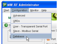
The Database screen displays the database where Historicals, reports are stored and it accepts possible changes in the digital outputs.
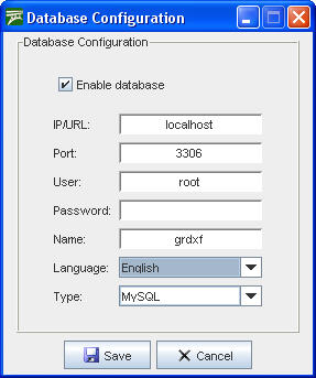
From here we can modify the configuration of the base, the IP address, the port, name and type of database (MySQL and SQL) containing the information and also configure the user and password so the MW can have access to the database.
|
The (MySQL o SQL) database must be created and the user configured for the MW must have read and write privileges enabled in the database. |
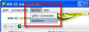
To determine the status of the database we can access the monitoring screen in Monitoring -> Database.
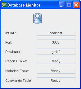
Database monitoring indicates the functioning of database tables and are presented in the following screen.
The IP address, the port and the name of the database must coincide with the data entered in the original configuration, then we find the three tables that make the database for the MW. If everything is working correctly, the three tables should indicate “Ready”, if this is not the case verify the IP address, the connection port, the user name and password; verify that the MySQL base is working and that the users have read and write privileges to access the database.
2022-03-17