Channels are the media through which information about inputs/outputs of the MW equipment are sent or received.
These channels can be linked to physical entry points of the equipment like MODBUD queries according to their compatibility with the channel.
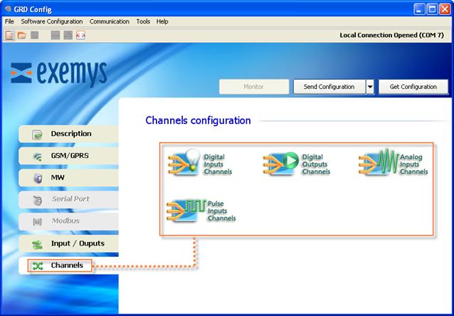
The ERD has 4 types of channels::
The most common option is to link them in the following manner:
Channel |
Input/Output |
I1 |
DI1 |
In |
DIn |
O1 |
DO1 |
On |
DOn |
AN1 |
AI1 |
ANn |
AIn |
P1 |
DI1 |
Pn |
DIn |
Where:
Ix: is a digital input channel.
DIx: is a physical digital input.
Ox: is a digital output channel.
DOx: is a physical digital output.
ANx: is an analog input channel.
AIx: is an analog physical input.
Px: is a pulse input channel. (Digital inputs are also associated to the pulse channel, since they can function in any of the two forms).
Beyond the most common way to link the channels like the previous example, it can be done in a disorganized manner or repeating them, this means that you could create a channel 15 linked with the D13 input and a channel 16 that is also linked to the D13 input.
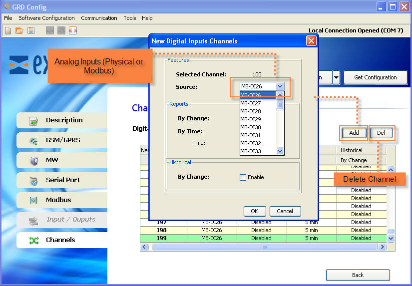
According to the ERD model the inputs /outputs could no be physical and come from MODBUS queries, in that case the link would be according to the type of query, for example, queries of the “coil” type could only be associated to the digital outputs channels, for more information on the type of queries and their association you must check with “GRDs incorporated MODBUS master”, in this case inputs/outputs would not be DIx, DOx or AIx but MB-DIx, MB-DOx or MB-AIx.
To add channels in the “Configurator” you must enter the menu “Channels -> Type of desired channel”.
After selecting the desired channel and among any of the 4 we’ll have the option to add or remove, it is important to point out that within each channel only inputs and outputs compatible with that channel will appear.
We will now see an example of how to add a digital input channel.