

For GRD-3G/4GA/4GM only |
GRD's serial port can be configured in Modbus slave mode. This mode will allow you to read and write all GRD channels (physical, Modbus or script)
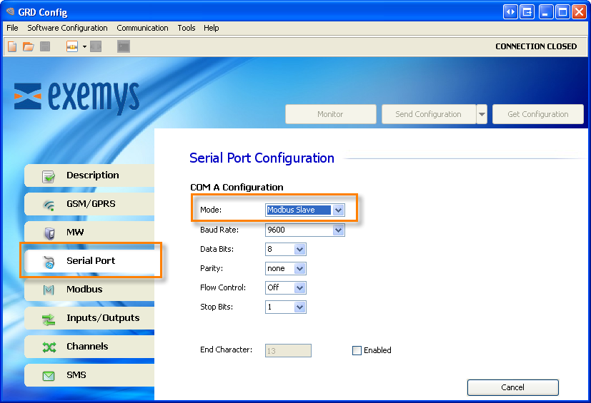
To use the Modbus slave configure one serial port in "Modbus Slave" mode
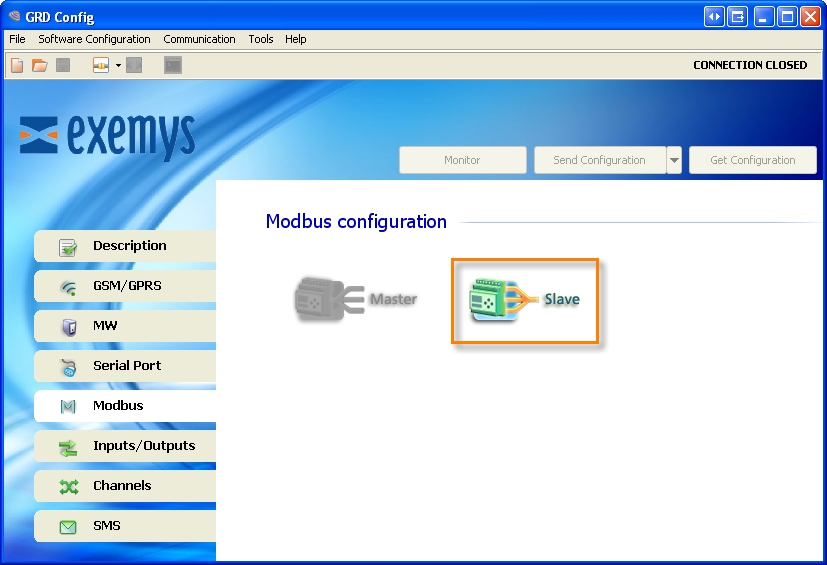
Go to the “Modbus” tab and select “Modbus Slave”
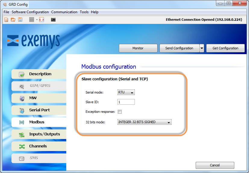
It refers to the Modbus protocol to be used, being RTU or ASCII.
The GRD will answer when it receives a Modbus query to this Modbus slave ID
If enabled the GRD will answer with an exception to a query sent with an invalid command, address range or value.
AN an P channels are mapped in 32 bit registers. Here you can configure if the most significant word is mapped in the first or the second register
This is how GRD channels are mapped
Start Address |
End Address |
GRD Channel |
Format |
10001 |
10100 |
I1 a I100 |
Bit |
00001 |
00100 |
O1 a O100 |
Bit |
40001 |
40200 |
AN1 a AN100 |
32 Bits integer |
40201 |
40400 |
PI1 a PI100 |
32 Bits integer |
Example. On a GRD3625-XF-3G/4GA/4GM or MQ with the default configuration the physical I/Os are mapped like this
Start Address |
End Address |
GRD Channel |
10001 |
10006 |
I1 to I6 |
00001 |
00006 |
O1 to O6 |
40001 |
40008 |
AN1 to AN4 |
40201 |
40212 |
PI1 to PI6 |
2022-03-17