

For GRD-3G/4GA/4GM only |
Depending on the GRD/cLAN model, it can have an internal Modbus master, which will allow you to increase the number of inputs/outputs of the device. We will now see the configuration and utilization.
This master will let you load a maximum of 100 Modbus queries to which will be able to configure certain parameters. Each one of the queries can be mapped as an input/output channel, and be able to configure the generation of Historicals and reports.
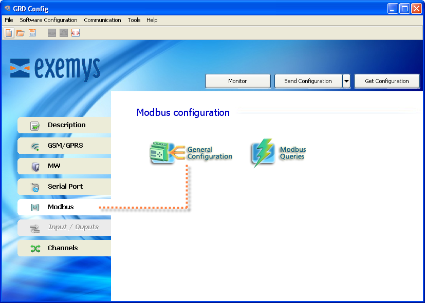
In “GRD Config” you will find a tab called “Modbus” where you can configure the general characteristics of the Modbus master and Queries.
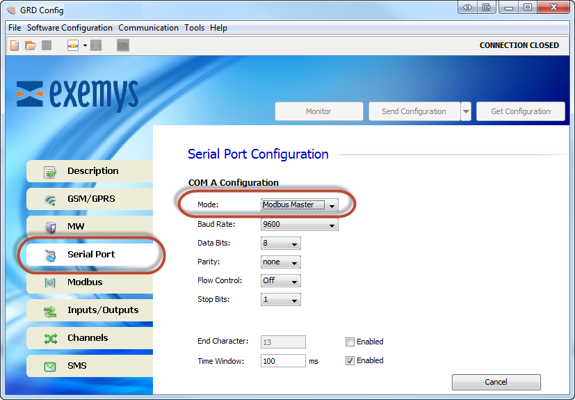
To use the Modbus master set the serial port in "Modbus Master" mode
Configure one serial port in "Modbus Master" mode
Inside the “Modbus” tab enter the “General Configuration” menu, where you can configure the Modbus master.
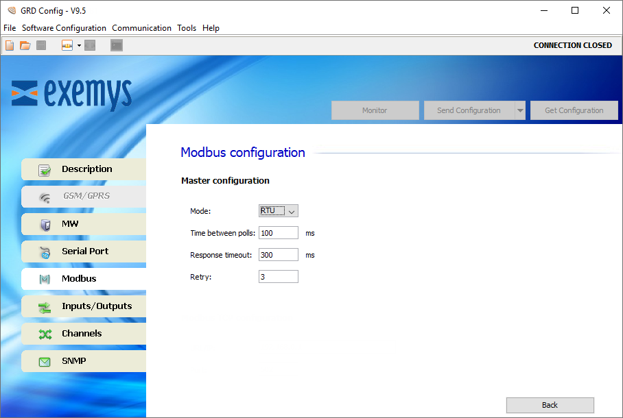
It refers to the Modbus protocol to be used, being RTU or ASCII.
This is the time the equipment will wait before sending a query after having received the response to another query.
This is the time the GRD/cLAN waits for the arrival of a response from the slave.
The retries are the number of times that the master will send the query if we don’t have a valid response, before considering the value of the query as 0, while the quantity of retries is not met, the master will maintain the previous value.
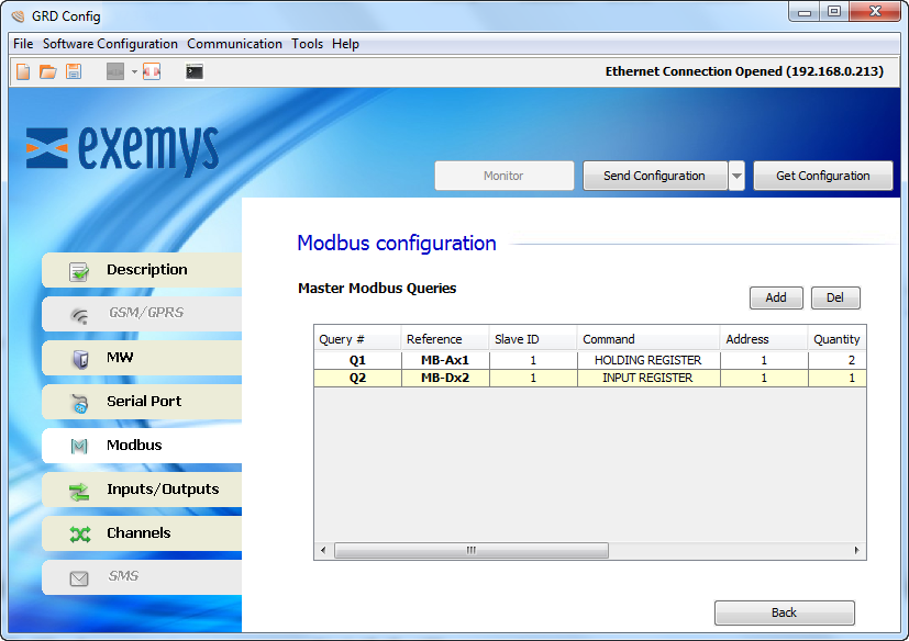
Once the master is configured we can add the desired queries entering the “Modbus Queries” menu and inside “Modbus”.
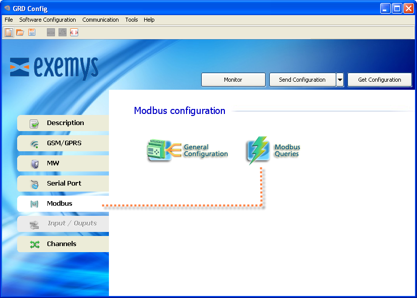
Inside the “Modbus Queries” a list will show us all the added queries and their parameters, which we will be able to modify. To add a query we click on “Add” or “Del” to erase it.
If we click on “Add” a screen will be displayed in which we will be able to configure all the parameters of the query
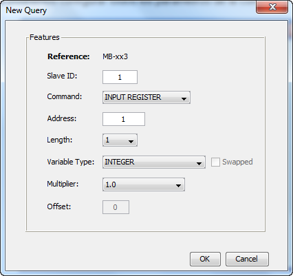
It is the address of the slave we wish to query.
Here we can configure the type of register to be queried:
In this parameter we load the address of the query, the value can be between 1 – 65536.
With this parameter we will be able to define the number of registers we want to query, this length can be 1 or 2 according to the type of query.
If the query is of the “Input Status” of “Coil Status” type, the length will necessarily be 1, that is, no modification will be allowed.
If the query is of the “Input Register” or “Holding Register” type, the length can be 1 or 2, implying that as a result of the query we will have 16 or 32 bits respectively.
This parameter is very important since it defines how the GRD/cLAN is going to store data received from a query. The types of variable that we will select depend on the type of queried register and its length.
The types are:
Registers will be ordered in a diferent way in querys with register length greater than one.
The offset can only be selected when we define the type of variable as “BIT WORD” this means that from a Modbus query that returns 16 bits we can keep the result of 1 bit. The value of this parameter goes from 0 to 15, being 0 the LSB and 15 the MSB.
We will now see the types of queries we can create and according to its parameters to which channel we will be able to add them.
Register type |
Length |
Data type |
Offset |
Channel |
Input Status |
1 |
BIT |
- |
I or O |
Coil Status |
1 |
BIT |
- |
I or O |
Holding Register |
1 |
BIT WORD |
0 to 15 |
I or O |
INTEGER |
- |
AN or PI |
||
INTEGER SIGNED |
- |
AN or PI |
||
2 |
INTEGER 32 BITS SIGNED |
- |
AN or PI |
|
| FLOAT 32 BITS | - |
AN or PI | ||
4 |
INTEGER 64 BITS | |||
FLOAT 64 BITS |
- |
AN or PI |
||
Input Register |
1 |
BIT WORD |
0 to 15 |
I or O |
INTEGER |
- |
AN or PI |
||
INTEGER SIGNED |
- |
AN or PI |
||
2 |
INTEGER 32 BITS SIGNED |
- |
AN or PI |
|
| FLOAT 32 BITS | - |
AN or PI | ||
4 |
INTEGER 64 BITS | |||
FLOAT 64 BITS |
- |
AN or PI |
2024-03-04