|
MQ models share the electrical specifications with XF models |
Depending on the application you will be able to choose from the following models:
Model |
Serial port |
Modbus master |
Digital Inputs |
Digital Outputs |
Analog Inputs |
Pulse count |
SMS alarms |
Script programming |
Power supply |
GRD1620-XF-3G / 4GA / 4GM |
1 x RS232/1 x RS485 |
Yes |
- |
- |
- |
- |
Yes |
Yes |
10 to 30Vcc |
GRD3621-XF-3G / 4GA / 4GM |
- |
Yes |
4(1) |
4(1) |
2 (4) |
4 (2) |
Yes |
Yes |
10 to 30Vcc |
GRD3625-XF-3G / 4GA / 4GM |
1 x RS232/1 x RS485 |
Yes |
6(1) |
6(1) |
4 |
6 (2) |
Yes |
Yes |
10 to 30Vcc |
GRD3534-XF-3G / 4GA / 4GM |
2 x RS232/RS485 |
Yes |
16 |
8 |
8 |
8 (3) |
Yes |
Yes |
10 to 30Vcc |
(1) Digital Inputs/Outputs are configurable and share the same terminals.
(2) Digital inputs can be use as pulse inputs.
(3) Some digital inputs can be use as pulse inputs.
(4) A PT100 temperature sensor can be connected to AI1
"3G" models bands support : GPRS: B2/B5, eGPRS: B8/B3, 3G: B1/B2/B5/B6/B8/B19
"4GA" models bands support (Latin America and Australia) : GPRS: B2/B5, eGPRS: B3/B8, 3G: B1/B2/B5/B8, LTE Cat 1:B1/B2/B3/B4/B5/B7/B8/B28
"4GM" models bands support" (Global) : GPRS: B2/B5, eGPRS: B3/B8, 3G: B1/B2/B4/B5/B6/B8/B19, LTE Cat 1:B1/B2/B3/B4/B5/B7/B8/B12/B13/B18/B19/B20/B25/B26/B28
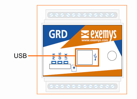
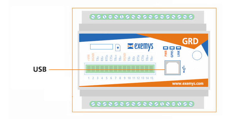
All GRD models have a USB communication port. This port is used to configure the GRD.
For the connection with the PC a type “B” USB standard cable is used.
GRD1620-XF-3G / GRD3621-XF-3G / GRD3625-XF-3G (4GA and 4GM models too) |
GRD3534-XF-3G (4GA and 4GM models too) |
|---|---|
 |
 |
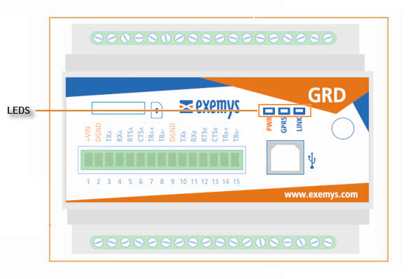
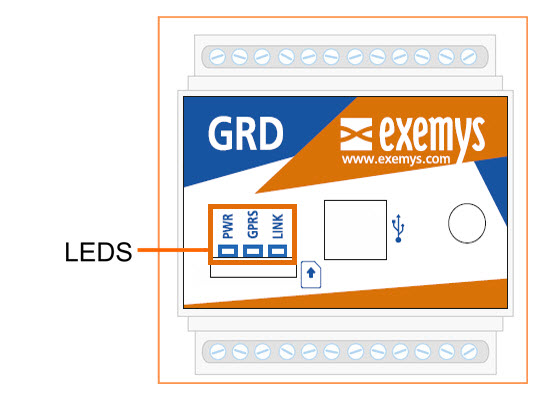
The GRD has 3 LEDs indicators.
PWR: Power applied to the GRD
GPRS: State of registration of the GRD in the GPRS network (GPRS, EDGE, 3G)
LINK: State of the connection between the GRD and the Middleware
GRD1620-XF-3G / GRD3621-XF-3G / GRD3625-XF-3G (4GA and 4GM models too) |
GRD3534-XF-3G (4GA and 4GM models too) |
|---|---|
 |
|
We find below the detail of the indication of each LED independently and in combination.
PWR LED |
GPRS LED |
LINK LED |
Description |
Fast blinking |
- |
- |
Connecting to the GSM network. |
On |
- |
- |
Connected to the GSM network if blinked previously otherwise SIM disabled. |
On |
Fast blinking |
|
Connecting to GPRS/3G/4G |
On |
- |
Connected to GPRS/3G/4G |
|
On |
Fast blinking |
Connecting to the MW |
|
On |
Connected to the MW |
||
Fast blinking |
SIM card missing |
||
On |
One blink |
- |
Sending or receiving a SMS |
On |
One blink |
Sending or receiving data via GPRS/3G/4G |
|
Sequencial blinking from left to right
|
Power on process |
||
On |
Slow blinking |
- |
Failure in connection to the GPRS/3G/4G retrying in a few seconds |
Blinking together with the LINK LED |
Alternate blinking with the PWR and LINK LEDs |
Linking together with PWR LED |
Low signal level |
|
|||
On |
Slow blinking |
Failure in connection with MW retrying in a few seconds |
|
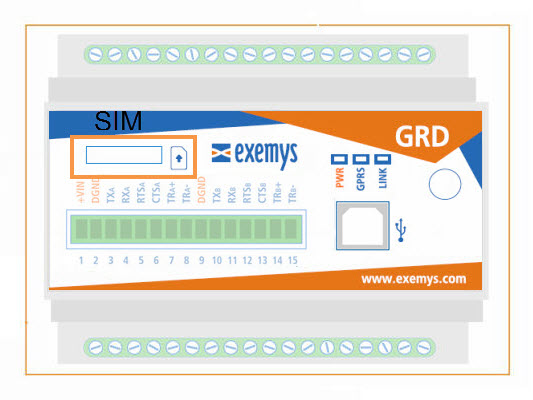
For the correct operation of the equipment the Micro SIM card must meet the following requirements:
A subscription to GSM and GPRS/3G/4G services
It must be cleared to be installed in any equipment (some SIM cards can only be installed in the equipment where they were purchased).
Verify the telephone number assigned to the SIM Card.
You must know the data to access the GPRS/3G/4G network of the telephone operator corresponding to the SIM card (APN, user, password). These data are preloaded in the GRD for Movistar Argentina, Telecom Personal Argentina and Claro Argentina. If you use another operator please contact support@exemys.com.
If the PIN (security code) of the SIM Card is activated you must enter it into the GRD when requested.
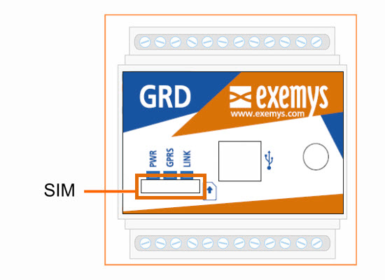
Place the SIM inside the GRD as shown in the figure or press it to remove
|
Do not insert o remove the SIM card while the GRD is powered on |
GRD1620-XF-3G / GRD3621-XF-3G / GRD3625-XF-3G (4GA and 4GM models too) |
GRD3534-XF-3G (4GA and 4GM models too) |
|---|---|
 |
|
2022-03-17