
Below are the minimum and maximum allowable values in both digital inputs and outputs, analog inputs for current and voltage, as well as in the wRemote power consumption.
Parameter |
Condition |
Minimum |
Maximum |
Units |
Input Voltage |
|
10 |
30 |
Vdc |
Average Current |
wTunnel @ 24 Vdc wTunnel @ 12 Vdc |
|
15 25 |
mA |
Maximum Current |
wTunnel @ 24 Vdc wTunnel @ 12 Vdc |
|
20 30 |
mA |
If the analog outputs are used in 0-10V mode, minimum voltage supplied is 13V to guarantee an output of 10V.
The maximum charge when using analog outputs in the current mode will be related to the input voltage too.
These specifications do not apply to the BP.
Parameter |
Minimum |
Maximum |
Units |
Frecuency |
2.4000 |
2.4835 |
GHz |
Channels |
|
16 |
|
Separation of Channels |
|
5 |
MHz |
Tx Power |
+10 |
+20 |
dBm |
Sensitivity |
-104 |
dbm |
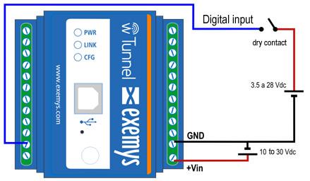
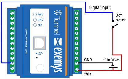
In order to activate the digital inputs external voltage must continue to be applied. This power supply has to share the GND terminal to the power supply of the device. If necessary you can use the same source that is used to supply the wRemote. The input type is Sinking and accepts sensors or PNP sourcing device types.
Parameter |
Minimum |
Maximum |
Units |
Activated Input |
3.5 |
28 |
Vdc |
Input Impedance |
2 |
|
KΩ |
Below are two examples of how to connect an input either directly from the same source that powers the device as well as an external source where it is clear that they must share the common terminal.
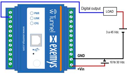
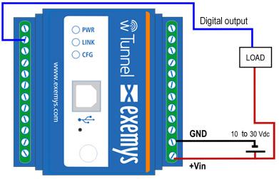
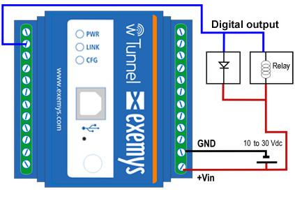
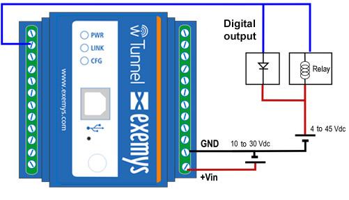
The digital outputs are open collector type. The load to be connected must be supplied with an external voltage source that must share the GND terminal to the power supply. If necessary you can use the same source that is used to power the device. The output type is NPN Sourcing (Open Collector).
Parameter |
Minimum |
Maximum |
Units |
Voltage Support |
|
45 |
Vdc |
Current |
|
50 |
mA |
When digital output is used to drive the coil of a relay, it is necessary to add to the connection a protection diode to prevent damage to the device output. This must be connected in reverse, which means to connect the anode to the output terminal of the device and the cathode to the positive terminal that supplies the relay.
The relay must be powered using an external power source, sharing the GND terminal with the source of the device, or if necessary can be used with the same source that feeds the wRemote. Shown in the following image below is the connection of a relay to a device’s digital output.
These specifications do not apply to the BP.
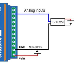
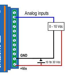
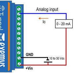
The analog inputs are referenced to the GND terminal of the device, so that the source that is used to power the sensor must share with the GND terminal with the device.
Parameter |
Value |
Units |
Full Scale |
10.00 |
Vdc |
Precision |
0.01 |
Vdc |
Input Impedance |
10.7 |
KΩ |
Below are two examples of how to connect an analog input voltage for both single sources as well as independent sources.
These specifications do not apply to the BP.
Parameter |
Value |
Units |
Full Scale |
20.00 |
mA |
Precision |
0.01 |
mA |
Shunt resistor |
68 |
Ω |
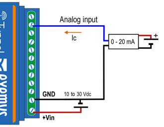
Below are two examples where you can see the connection of a 4-20mA sensor sharing the power source with the device for passive sensors or active sensors with an independent source.
These specifications do not apply to the BP.
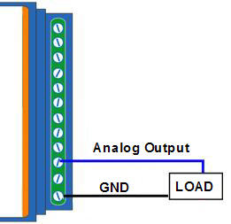
The analog outputs are referenced to the GND terminal of the device.
The analog outputs in voltage mode have the limitation that the charge that we put must be less than 500R if we use the full range of the output voltage and can deliver a maximum of 20mA.
You should always follow VoutMAX / Charge <= 20mA
Type of connection:
These specifications do not apply to the BP.
In this case the maximum charge that we can connect to the analog output in the current mode depends on the voltage supplied, as this should be enough to deliver up to 20mA to the charge.
Power Source (V) |
Max Load. |
13 |
650R |
15 |
750R |
24 |
1,2K |
30 |
1,5K |
Type of connection:
These specifications do not apply to the BP.