

The wTunnel-3002-BP is a “Tunnel” model whose main difference from other models is that this model is “Low Power” and is powered by an internal battery whose autonomy depends on the measurements that are made.
The principal function of this model is similar to the standard “tunnel”; the difference is that this only works as “Type B” and is placed in lower power mode. It turns on when it needs to measure one or more analog inputs and transmit the data to “Tunnel A”. This means that the device will turn on depending on the setting of the “Report on Time” for each of the entries. So it will turn on to report any change in a digital input.
The device uses a network search criteria to save battery, it searches for a network for 1 minute and if not found will be placed in low power mode for 2 minutes. It will then retry and if it still fails the search time will remain in low consumption increasing with the sequence 2min. – 5min. – 10min. – 15min. – 30min. – 1hr – 2hr and finally will be left at 4 hours. Using the same criterion in case the device finds a network but it’s not authenticated.
If you connect the USB cable to any device “host” it will try to connect permanently ignoring the above criteria.
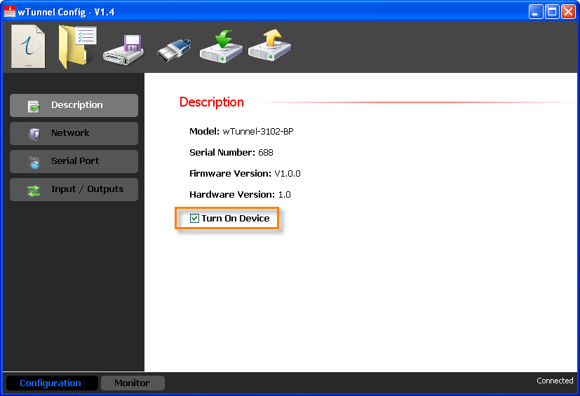
Like the first difference with the standard “Tunnel”, the “Battery Powered” has an additional parameter that is the “Turn on Device” which allows us to turn on or turn off the device.
When the check mark is not placed it only functions as USB communication, in this mode the device can be stored and the consumption of battery power will be almost zero. If we put the check mark the device will start working normally, lighting up the communication module and the inputs and outputs.
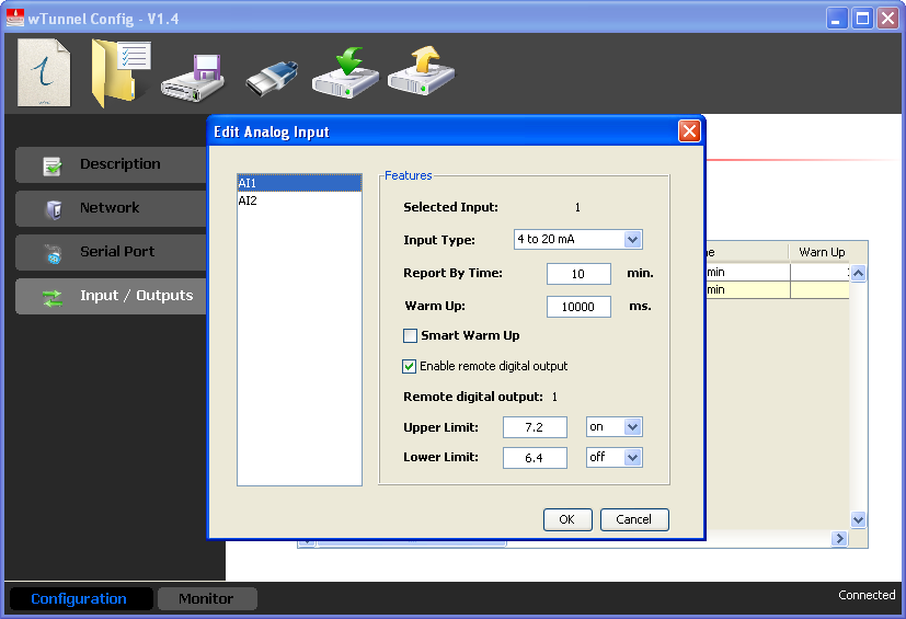
Here is the analog input configuration that differs from that of the standard “Tunnel”.
In the configuration we can define:
Report Time
Warm up time, referred to as how much time it is going to need to start up and power outputs (VOUT1 or VOUT2) corresponding to the analog input to measurements.
On this screen we can see the monitoring of digital and analog inputs and the counters. We can also use the “ON” button to turn the power corresponding to each of the analog inputs on or off.
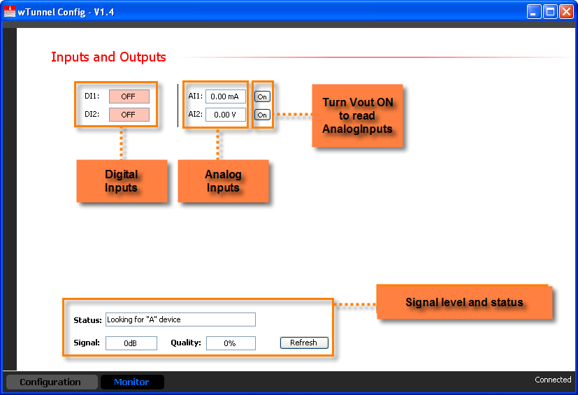
When connecting the USB cable and enter the monitor screen, if the device is connected to the “Tunnel A” we see that the measurement of the analog inputs is not simultaneous but sweeps by all that are available and samples the amount of time that it is set to “Warm Up” so that after, each measurement I transmitted regardless of the value of the reporting period.
If the computer is offline, the measurement is simultaneous but does not turn the power output of each sensor. We will have to manually activate them using the corresponding “ON / OFF” buttons.
Continues we will see how to connect the different types of I/O’s that the devices have.
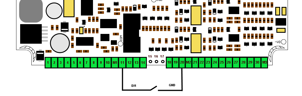
In order to activate the digital inputs we must apply GND.
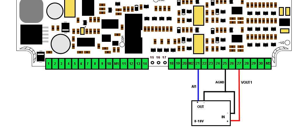
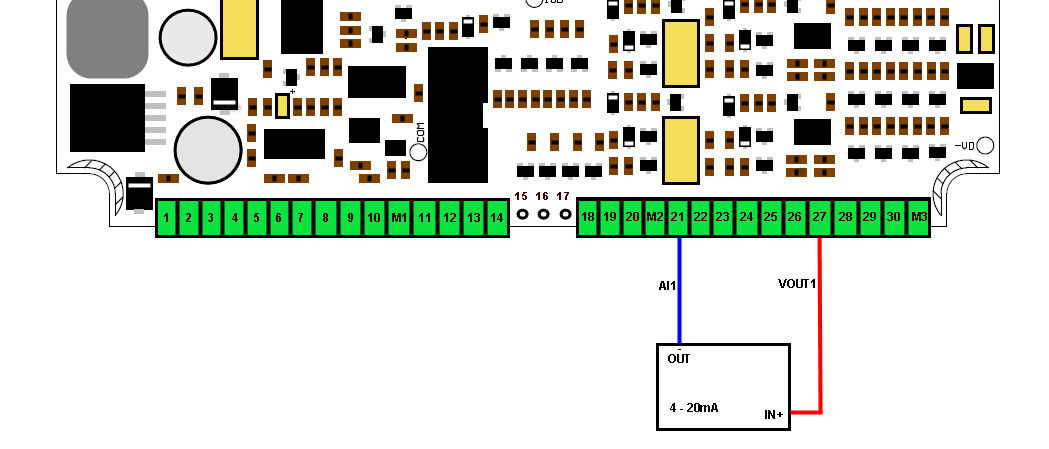
The analog inputs refer to the GND Terminal of the device and each one has an associated VOUT output of power to supply the sensors.
VOUTx outputs are not regulated and may vary from 15 to 24Vdc depending on the load. It will deliver a maximum of 22mA.
Parameter |
Value |
Units |
Full Scale |
10.00 |
Vdc |
Precision |
0.01 |
Vdc |
Input impedance |
10.7 |
KΩ |
Parameter |
Value |
Units |
Full Scale |
20.00 |
mA |
Precision |
0.01 |
mA |
Shunt resistor |
62 |
Ω |
Continuing we will see a curve that allows us to determine the battery life of the device depending on the digital inputs are conducted.
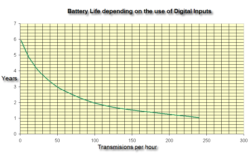
To use it we estimate how often the digital inputs will change in one hour. With this we enter the table number on the X axis and the autonomy (battery life) in years results on the Y axis.
Then see how to use the curve for a configuration using only analog inputs.

In this case we must determine how long the device is turned on per hour. For this we must calculate how often an analog input is measured per hour, this number is multiplied by the warm up time and should be done with all entries. They should then be summed and the result entered into the table.
Example
AN1 configured with “Report Time = 15min”, here we have 4 times per hour and “Warm Up = 2sec”. With these two values the startup time per hour of AN1 is 4 x 2 = 8sec.
Suppose the AN2 is set to “Report Time = 30 min”, here we have 2 times per hour and a “Warm Up = 3sec”. With these two the startup time per hour of AN2 is 2 x 3 = 6sec.
As a last step we ass the two times together, 8 + 6 = 14 seconds. We then enter this into the table to obtain the battery life.