Depending on the application you will be able to choose from the following models:
Model |
Serial port |
Built-in MODBUS master |
Discrete Inputs |
Discrete Outputs |
Analog inputs |
Counting inputs |
ERD2401 |
RS232/RS485 |
Yes |
6 |
2 |
- |
6* |
ERD3404 |
RS232/RS485 |
Yes |
- |
- |
8 |
- |
* Discrete inputs can work as counting inputs
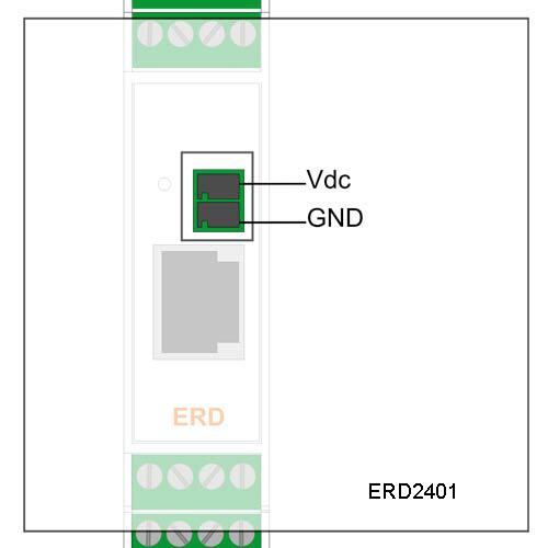
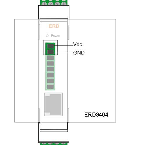
Terminals 1 and 2 correspond to power supply.
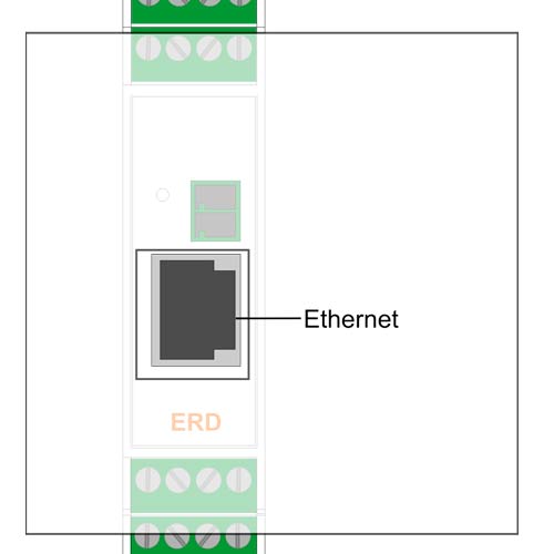
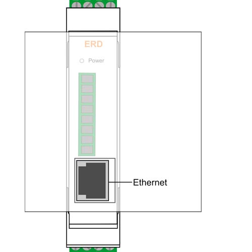
All ERD models have an ethernet communication port. This port is used to configure the ERD and to establish the connetion to the MW.
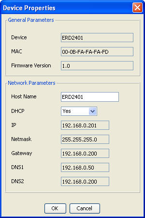
The ERD can acquire it's network configuration using DHCP, but you can set it manually.
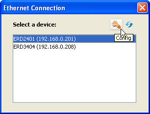
After clicking on the icon you will see this window where you can enable/disable DHCP and configure the network paramateres manually.
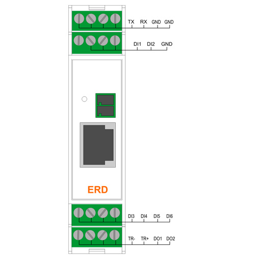
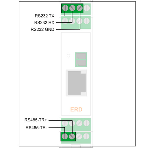
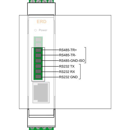
The RS232 port is of the 3-wire DTE type (TX, RX, GND) and has a terminal board for its connections.
The RS485 port has 2 terminals (TR+ y TR-)
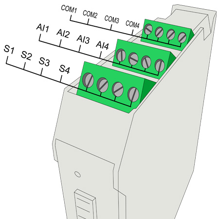
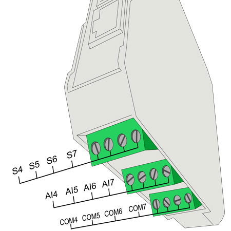
We now indicate the terminal board for the connection of inputs and outputs and power supply of the ERD depending on the model.
- ERD3404
- ERD2401
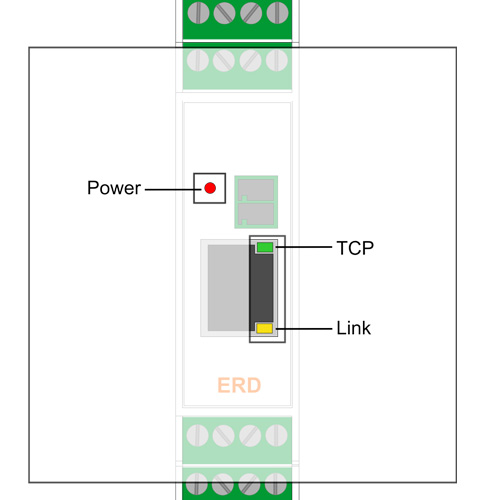
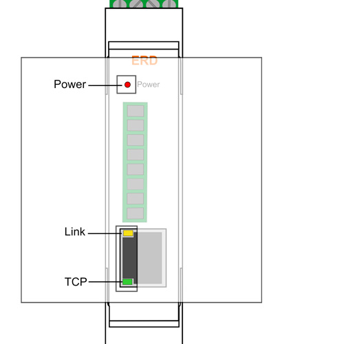
The ERD has 3 LEDs indicators.
RED: Power applied to the ERD
Yellow: State of registration Ethernet Link
Green: State of the connection between the ERD and the Middleware
We find below the detail of the indication of each LED independently and in combination.
YELLOW |
GREEN |
Description |
1/2 second on, 1/2 second off |
- |
Time to access serial console |
ON |
ON |
Booting or erasing the memory |
Alternate blinking with the GREEN LEDs |
Alternate blinking with the YELLOW LEDs |
Critical failure (contact support@exemys.com) |
1/10th second on, 9/10th second off |
- |
Valid IP address and ethernet link |
Blinking fast |
OFF |
Ethernet disconnected |
- |
Blinking fast |
Connecting to the MW |
- |
ON |
Connected to the MW |
- |
Single blink OFF |
Sending/Receiving data to/from the MW |