

We will now see how to configure in the MW the ERDs that we use to multiplex MODBUS. In this mode of operation the MW will receive the “MODBUS TCP” queries sent to the port/s of the “Modbus Server” which will resend to the ERD with the slave being queried.
|
Slave number 247 is reserved for use by the “MW internal slave”. |
We must first have the MW connected and the ERD added as indicated in “Connection between the ERD and MW”.
We have 2 Modbus (RTU) devices connected in port RS485 of the ERD with GRD ID = 10 without a password.
Device 1: ID Modbus 43 (query from port 502)
Device 2: ID Modbus 66 (query from port 503)
We also have 1 Modbus (ASCII) device in port 232 of the ERD with GRD ID = 13 without password.
Device 1: ID Modbus 87 (query from port 504)
MW data: (These parameters are configured in the MW connection).
Modbus Port: 502
Number of ports: 3
In the MW we enter in “Configuration -> ERDs” and we edit the “Serial port mode” placing it in “MODBUS”.
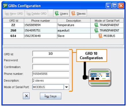
When you press the save button it is stored in the list of valid ERDs. The mode must be Modbus for it to work in this manner. The following figure shows the addition of the other ERD and in the upper part the ERD added previously.
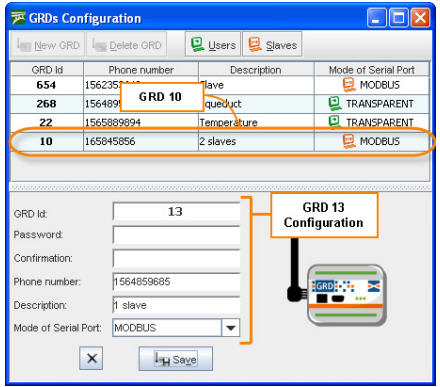
Once both ERDs are incorporated to the list we can assign them the corresponding slaves to each one and also indicate what type of Modbus protocol will be used.
To be able to add the slaves to each ERD we have to enter the Administration screen of ERDs Modbus and slaves, we place the cursor on the ERD in the upper part and press the +Slaves button; a window will open as the one shown in the figure below where you enter the number of the slave connected to the ERD in its serial port and the port number of the Modbus server from where the query will be made to that slave.
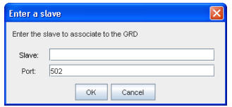
Once the corresponding slaves and its port are entered, the Modbus protocol to be used must be selected, which could be RTU or ASCII.
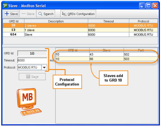
As it can be seen in the previous figure the ERD 10 has 2 ModBus slaves. We also determine the communications protocol, that in this case is RTU, the Timeout of the communication and then we press the save button to store the changes. The purpose of Timeout is to prevent the system from waiting for a response for an undetermined time, this time is expressed in milliseconds, therefore, when a query is sent, this is the maximum waiting time for a response, once this time is up the systems discards all the responses from that ERD until a new query occurs.
|
Verify that the Modbus master timeout is less than the configured Timeout for the ERD to avoid losing responses to the queries. |
In the same manner, the slaves are added for the following ERD, but in contrast to the previous one, this one has an ASCII communication protocol.
The communication protocol is determined by the devices connected to the ERD, this means that, the required communication protocol will depend on the device to be connected.

In this manner, the two ERDs are configured from the MW side and working according to what was established in the beginning.