The “Concentrador” has an internal Modbus slave containing the value of the inputs and outputs of the equipment “Nodes” connected to it. The values that are read from the slave are only those that correspond to reports from wRemote “Nodes”. Later we will see when and what reports are, that are generated.
In the same way in which queries are performed, external slaves also perform internally; the ID of the latter is configurable. The slave has on your map the values of “Connection Status”, “Digital Inputs”, “Digital Outputs”, “Analog Inputs”, and “Analog Outputs”. We are also able to change the value of the outputs written to corresponding registers. If you enter a record pertaining to an input that will give us an exception, we are unable to make the entry.
Queries can be conducted for example from a SCADA or any Modbus Master that connects to the “Concentrator”.
Then we will see the configuration in the “Concentrator” and “Nodes”
The Modbus master can be connected to the “Concentrator” using Port Series 232 / 485 or a USB.
The “Nodes” have digital inputs and outputs as well as analog inputs that can be connected to different devices, as we saw in “Installation”.
Configuration of the Concentrator:
Assuming the network is formed and the “node” devices are linked we look at the following example:
Serial Number: 125
Internal Slave Number 230
Connected to the master that sends queries in MODBUS RTU at 115200 baud.
Serial Number:: 126
ID: 5
Serial Number:: 124
ID: 2
The topology of this example would be as follows:

As we saw above, each “node” has an “ID” number that is used to locate the values of their inputs / outputs on the internal Modbus slave table.
The “Node” with serial number 126 has the “ID” 5
The “Node” with serial number 124 has the “ID” 2
Now go to the tab “Serial Port” in the “Concentrator” and configure it as we specified in the Modbus RTU example, 115200 bauds, we must also take into account flow control, parity, etc.

After that, go to the Modbus tab where we configure the internal slave number which for this example is 230.
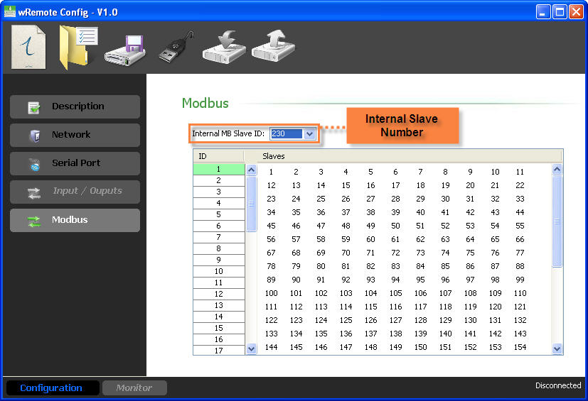
Once finished, send the configuration to the “Concentrator”.
Configuration of the Nodes:
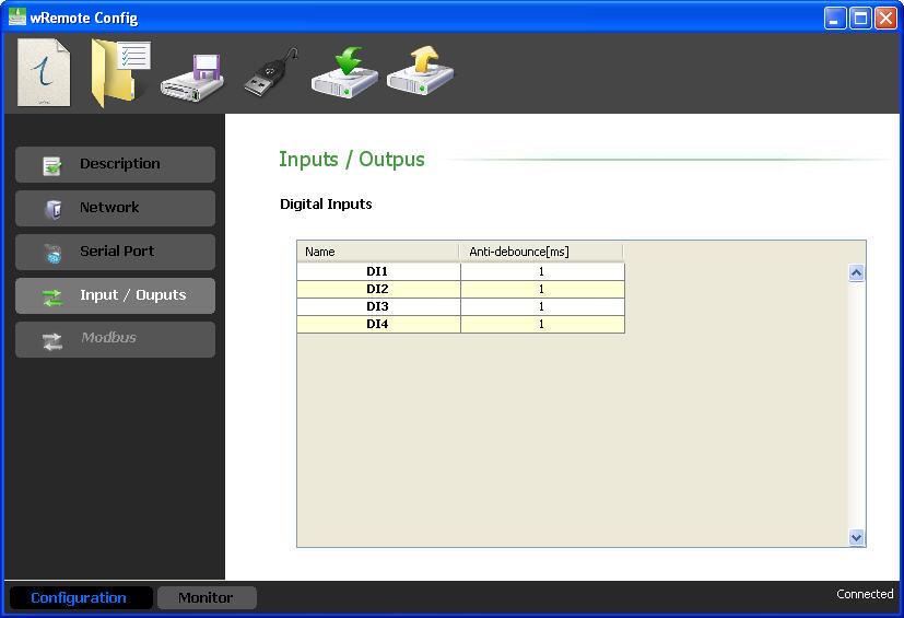
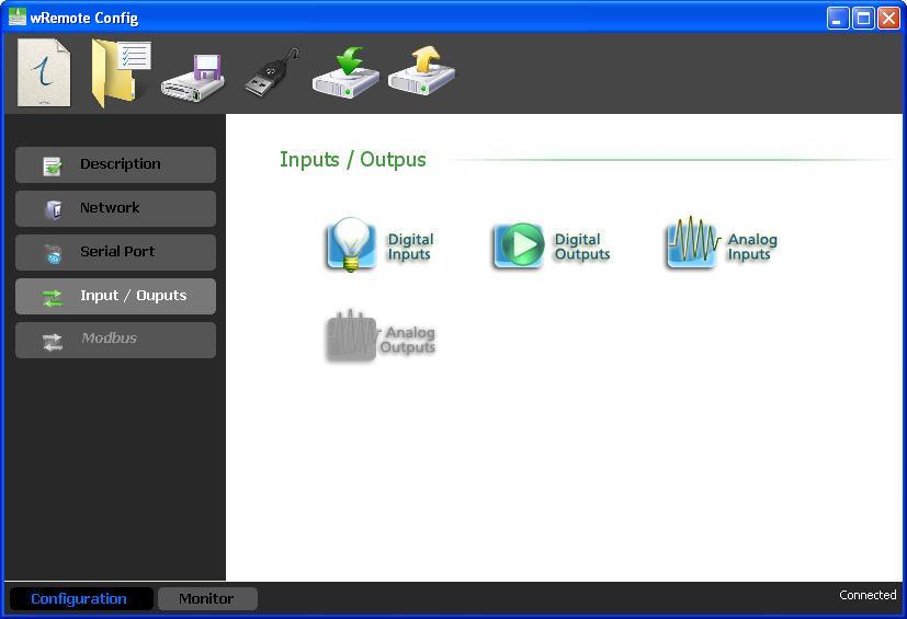
In the “Nodes” we have to configure the inputs / outputs according to our needs. For this we must connect locally or remotely to the “Node” device with the “wRemote Config”. Read the configuration and in the tab “Inputs / Outputs” we will find the different types to configure.
In this case, if the device orders a count entry we can configure if we want it to be reported or leave it without change. We can also select the count divider and define how often we want the counters to report.
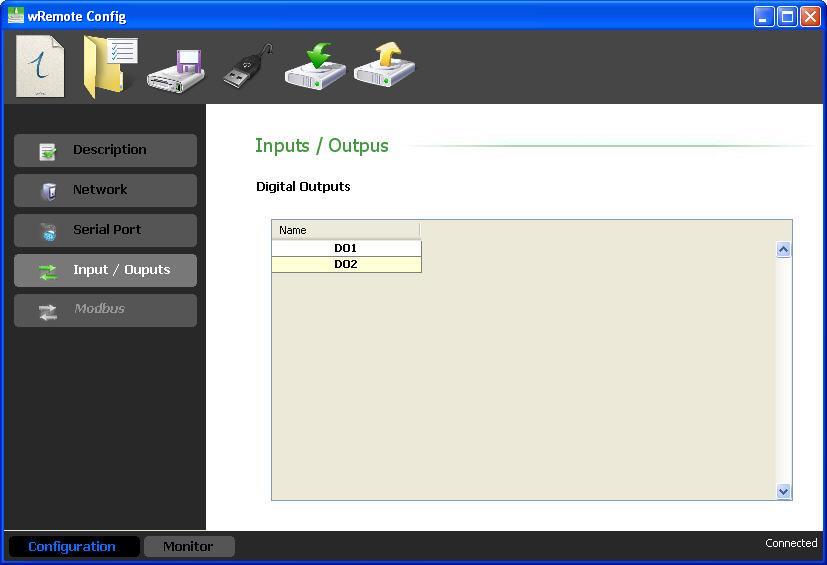
In this case we do not have anything to configure and the criteria reported is also for change.
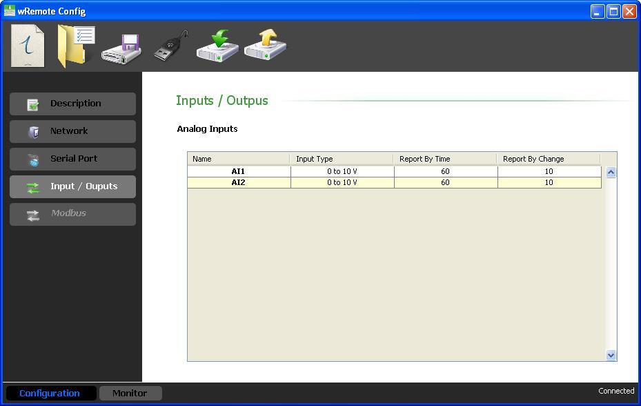
Here we must configure the type of input 0-10 V or 4-20 mA. Now we are able to select the report criteria, one of which is time in seconds which disables making 0 the time and another is by percentage of change with respect to the full scale and disables placement in 100 percent.
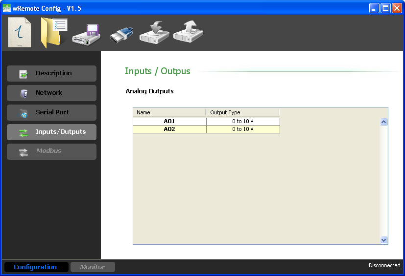
Here we must configure the type of output 0-10 V or 4-20 mA, the value of these reports to the “Concentrator” every time that they change.
Once configured the inputs / outputs and the “node” device report criteria, they will begin to send them to the “Concentrator” for the updated values in the internal slave table..
|
It is important to know that all of the “Nodes’” parameters report to the “Concentrator” every time they connect, beyond the configured criteria report. |
Already having configured all devices, we will see how to query the values of inputs / outputs to the internal slave of the “concentrator” and how they are organized.
Organization of the HOLDING REGISTERS:
Register Number |
Information |
Register 1 |
State of connection |
Register 2 |
Digital Inputs |
Register 3 |
Digital Outputs |
Register 4 to 7 |
Analog Inputs / Counters |
Register 13 to 16 |
Analog Outputs |
In each operation we are able to query with a maximum of 64 records if we query more we will obtain a Modbus exception response.
The calculation to determine the address of a record for a given remote is as follows:
Register X = 40000 + (wRemote_ID – 1) * 16 + Register Number (1 to 16)
As an example suppose we want to read the analog input 3 from the wRemote “Node” that has the ID=5. Therefore the analog input 3 corresponds to the record 6.
Register 6 (wRemote 5) = 40000 + (5 - 1) * 16 + 6
In order to meet the desired value we must access the 40070 record.
The inputs and outputs are grouped into two records, 2 for the inputs and 3 for outputs, which contain in bits the corresponding values. Knowing that the wRemote input 1 corresponds to bit 0 of the register and input 4 corresponds to bit 3, we can determine each one in the same manner that exits are located.
To know the status of the connection allows us to read register 1 at bit 0. If this is found in 1 it indicates that the device is connected, while if set to 0 indicates that the device is offline.
Depending on how they are configured the values of analog inputs that take records will be from 0-1000 voltage and 400-2000 current. In these records we also have the values of the counters which depend on the configuration of the “Node” or if the node was configured to transmit the analog input or counter. For example if you have a model with 4 analog inputs and 4 counter inputs we can only transmit 4 of these 8. So in the “Node” you can enable one or the other particularly if we transmit the AN1, we cannot send the PI1 and if we enable the PI2, we cannot do it with the AN2 and so on.
The pulse counter value range is 0 to 49999. After 49999 it will roll over to 0.
From here you can change the value of the analog and digital outputs.
Organization of the INPUT STATUS:
In the Input Status we can also find out the status of digital inputs for all of the wRemotes.
In every operation we can query at most 64 inputs, if we query more we will get a Modbus exception response.
Each wRemote occupies 16 positions and the calculation to read the values of one input is as follows:
Input X = 10000 + (wRemote_ID – 1) * 16 + Register Number (1 to 16)
For example if we wish to know the wRemote input value 4 having the ID = 2, the calculation is as follows:
Input 4 (wRemote 2) = 10000 + (2 - 1) * 16 + 4
Equivalent to Modbus address 10020.
Organization of the COIL STATUS:
In the coil status registers we visualize the digital outputs of the equipment.
In every operation we can query at most 64 coil, if we consult more we will get the Modbus exception response.
To determine the address of the outputs for each wRemote calculated.
Output X = (wRemote_ID – 1) * 16 + Output Number (1 to 16)
For example, if you want to access the wRemote output 2, that has the ID = 10 the calculation is as follows
Output 2 (wRemote 10) = (10 – 1) * 16 + 2 = 146
Equivalent to the 00146 Modbus address of the coil status.
If we write about these records amending the output status of wRemote “Nodes”.
Another way we display the values of the inputs / outputs of the “Node” equipment is to connect with the “wRemote Config” to the “Concentrator”. Read their parameters and then go to the “Monitor” window, there we will click on “MB Table” and we will see:
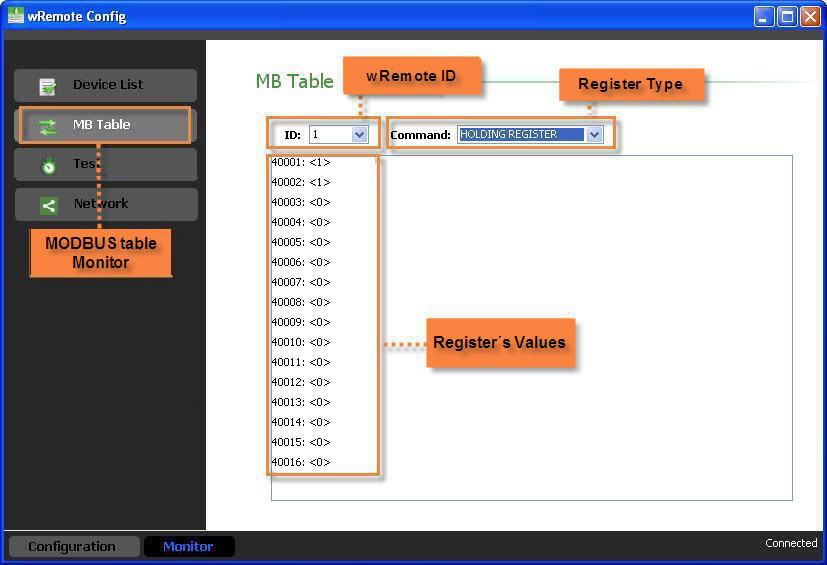
Here we can consult the Holding Registers, Input Status, Coil Status by selecting each ID as seen in the image.
2022-06-22