

Model |
Serial Port |
Digital Inputs |
Digital Outputs |
Analog Inputs |
Analog Outputs |
Power Supply |
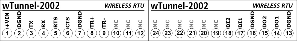
wTunnel-2002 |
RS232/RS485 |
2 |
2 |
- |
- |
10 to 30Vdc (external) |
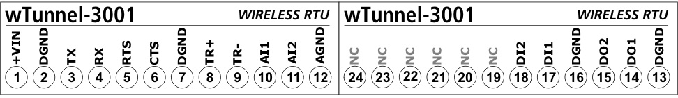
wTunnel-3001 |
RS232/RS485 |
2 |
2 |
2 |
- |
10 to 30Vdc (external) |
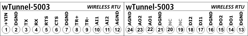
wTunnel-5003 |
RS232/RS485 |
2 |
2 |
2 |
2 |
10 to 30Vdc (external) |
wTunnel-3102-BP (*) |
- |
2 |
- |
2 |
- |
Built-in Lithium Battery |
(*) This model can only be configured in mode B
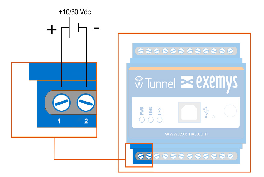
The terminals 1 and 2 correspond to the power source.
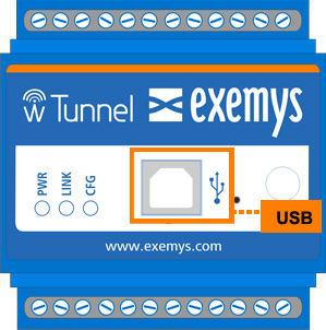
All of the w Tunnel models have a USB communication port. This port is used for the configuration of the device or the transmission of data. For the connection with a PC use a standard type “B” USB cable.
USB port in standard models:
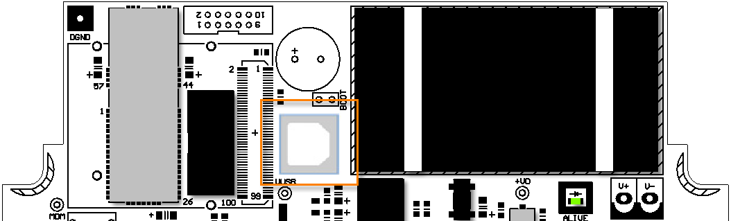
USB port in BP models:
|
Attention, if you connect the USB port will be disabled RS232/485 serial ports. |
The RS232 port is of the DTE type 5-wire (TX, RX, RTS, CTS, GND) and has a terminal block for its connection, and terminals TR+ and TR- for RS485.
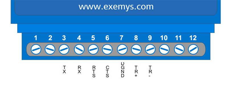
It is not necessary to connect the CTS and RTS pins if you are not going to use flow control.
Below are the input and output terminals and wTunnel power source depending on each model.

PIN |
Function |
3, 4, M1, 15, 20, M2 |
DGND |
25, 26, M3 |
AGND |
11 |
DI1 |
12 |
DI2 |
21 |
AN1 |
22 |
AN2 |
27 |
VOUT1 |
28 |
VOUT2 |
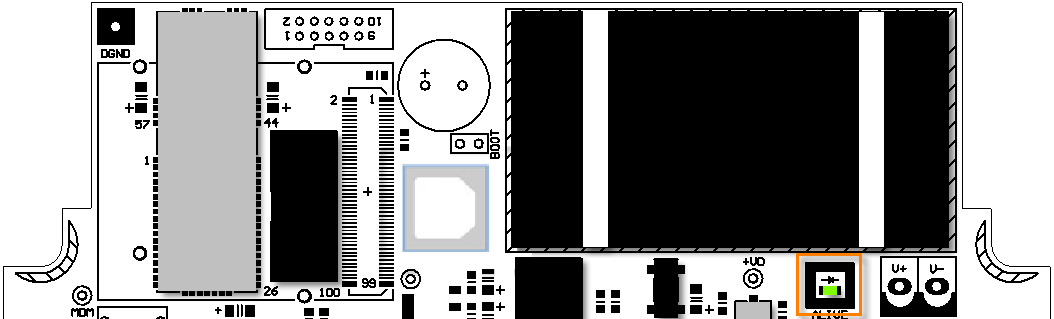
4-20 mA / 0-10V analog inputs jumper configuration on wTunnel-3001 hardware V1.0
In the models belonging to this version of hardware, they should be selected if the analog inputs will be of the 0-10V or 4-20mA type with internal jumper devices. Carefully disassemble and place the jumpers to the right for 4-20mA or left for 0-10V as shown in the figure.
Remember that you must then configure the wTunnel from the configuration software indicating the type of input that you are using.
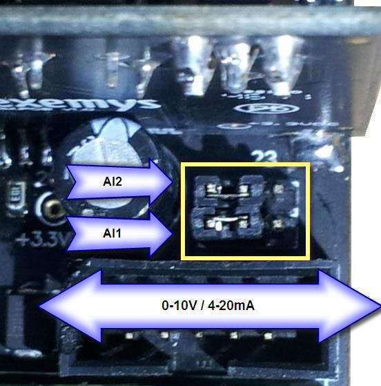
All other models have software configurable analog inputs
|
Attention, if a voltage is injected directly into an analog input and it is configured as 4-20mA, it may cause damage. |
The wTunnel has 3 LEDs indicators.
POWER: Energy applied to the wTunnel
LINK: Network Status
CFG: Configuration Mode
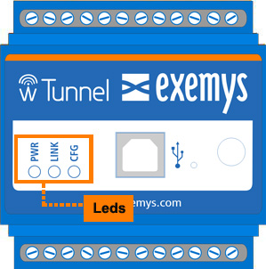
Below the details of each LED in independent form and in combination are shown.
PWR LED |
LINK LED |
CFG LED |
Description |
On |
- |
- |
Device on |
On |
Slow blinking |
Creation or connection of a network | |
On |
Fast blinking |
|
Mode A: Network created, waiting for B device. Mode B: Connected and in authentication process |
On |
- |
Mode A: Network created, B device connected Mode B: Connected and authenticated |
|
On |
- |
On |
Configuration |
Fast blinking |
Fast blinking |
Fast blinking |
Critical Failure |
Fast blinking |
Off |
Fast blinking |
Serial Number not configured |
Fast blinking |
Slowblinking |
Fast blinking |
Model not configured |
LED Indicator in BP models:
In this case, the LED flashes every 10 seconds indicating that the equipment is in operation.
The wTunnel has a reset button; to activate it you must have a cylindrical device that is small / adequate in diameter as the button is inside the device. In the image we can see its location.
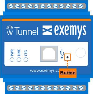
This button serves to reset the device’s network connection.